Load Dispersion at Wall Ends and Openings
22 October 2026 · 4 min read
How LoadTakedown disperses loads near wall ends and jambs so that each load's resultant stays in place, and why this matters for walls supported on beams.
Loads applied to a masonry wall are normally dispersed at 45° to the vertical on each side as they pass down the wall. Near a wall end, or beside a window or door, part of that dispersion falls outside the wall. The common corrections are to fold the excess back into the wall or to cut it off and scale up the remainder. Both preserve the total load but move its resultant. For a wall on a foundation this alters only the pressure distribution. For a wall supported on a beam, it alters the support reactions.
Example: wall on a beam
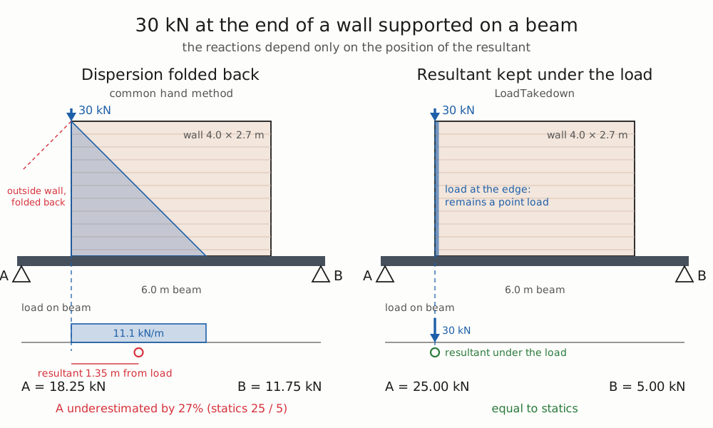
A wall 4.0 m long and 2.7 m high is supported on a 6.0 m simply supported beam, with each end of the wall 1.0 m from the adjacent support. A 30 kN load is applied at the top of the wall, at the end nearest support A. The reactions depend only on the position of the load's resultant, so by statics:
B = 30 × 1.0 / 6.0 = 5.0 kN
A = 30 − 5.0       = 25.0 kN
With 45° dispersion through 2.7 m of wall, half the dispersed load falls beyond the wall end. Folding it back gives:
Dispersed load   30 / 5.4 = 5.56 kN/m over 5.4 m
Folded back      11.1 kN/m over the first 2.7 m
Resultant        2.35 m from A (1.35 m from the load)
B = 30 × 2.35 / 6.0 = 11.75 kN
A = 30 − 11.75      = 18.25 kN
Reaction A is underestimated by 27%. For a load at the wall end, cutting the excess and scaling the remainder gives the same result.
Reactions A / B (kN) for the same load at a range of positions:
| Load from wall end (m) | Statics | Folded dispersion |
|---|---|---|
| 0 | 25.00 / 5.00 | 18.25 / 11.75 |
| 0.3 | 23.50 / 6.50 | 18.17 / 11.83 |
| 1.0 | 20.00 / 10.00 | 17.32 / 12.68 |
| 2.0 | 15.00 / 15.00 | 15.00 / 15.00 |
LoadTakedown gives the statics values at every position.
Method
LoadTakedown first disperses each load at 45° and folds back any part that passes a wall end or jamb. Where the fold moves the load's resultant, part of the load is redistributed as a triangular stress block at that edge, in the proportion that returns the resultant to the load position. The triangle is 2.7c long, where c is the distance from the edge to the load. A load whose dispersion stays clear of the edges, or which covers the full wall length, is unchanged. As a load approaches an edge, the triangle carries more of it: for 30 kN at 0.3 m from a wall end, 2.7 m below the load, 97% of the load forms a triangle 0.81 m long with a peak of 72 kN/m. A load at the edge itself remains a point load. The distribution varies continuously with load position and depth.
The edge triangle is based on the no-tension stress block used in BS 5628 bearing checks for a concentrated load near a wall end. That check applies it only at the bearing; LoadTakedown uses it at every depth so that the resultant stays under the load.
The same rule applies to point loads, line loads and self-weight. For 10 kN/m over the end 1.0 m of the example wall, the reactions are 7.50 / 2.50 kN, equal to statics; folding alone gives 5.98 / 4.02 kN. In addition:
- Openings: each jamb is treated as a free edge, in the same way as a wall end.
- Lintel reactions act at the centre of the lintel bearing (150 mm by default, so 75 mm from the jamb) and are dispersed from there.
A simply supported beam under the wall therefore receives the statics reactions of each load, wherever it acts. Bending moments in the beam still depend on the dispersed distribution.
Foundation pressures
Loads are dispersed separately, each without tension, and the results are summed. Where several loads act near a wall end, the summed pressure exceeds that of the wall analysed as a single body. For a single-storey wall 6.0 m long and 2.7 m high, with self-weight 11.4 kN/m and a 10 kN/m variable floor load over the first 1.0 m at the top (unfactored G + Q):
Total         11.4 × 6.0 + 10 × 1.0 = 78.4 kN
Resultant     2.68 m from the loaded end
Eccentricity  0.32 m (within L/6)
Single body   78.4 / 6.0 × (1 + 6 × 0.32 / 6.0) = 17.2 kN/m
| Method | Pressure at loaded end (kN/m) |
|---|---|
| Vertical (no dispersion) | 21.4 |
| Single body | 17.2 |
| LoadTakedown | 25.6 |
Peak pressures near wall ends and openings are therefore conservative. In a study of 400 randomly generated walls with full self-weight, the peak was typically about 1.1 times the single-body value and at most about 1.75 times; on lightly loaded walls it reached about 2.8 times. It was never lower. Totals per load case, foundation totals and the reactions of simply supported beams are exact. LoadTakedown states this on the stress views and wall base results.
A point load very close to a wall end gives a high local base pressure in any tension-free distribution: with its resultant a distance a from a free edge, the pressure at the edge must reach at least P/2a. For 30 kN at 0.15 m that is 100 kN/m; LoadTakedown gives about 146 kN/m.
Limitations
- The dispersion angle is a project setting, 45° to the vertical by default. EN 1996-1-1 clause 6.1.3 uses 60° to the horizontal for concentrated loads. Individual walls can be set to transfer loads vertically.
- Composite action between a wall and its supporting beam (BS 5628-1, clause 35) is not considered.
- Bearing stresses under padstones and lintel ends must be checked separately.
Sketch your structure straight onto a PDF plan and get tributary loads for every wall and level, instantly.
Open LoadTakedown