Walls That Don't Line Up: Load Takedown for Offset Walls
9 October 2026 · 7 min read
When a first-floor wall isn't over a wall below, the floor supports it and distributes its load sideways. Worked cases: a 62/38 split and a 14 kN point load.
If a loadbearing wall upstairs does not sit directly over a wall downstairs, its load is supported by the floor it stands on and distributed sideways to whatever holds that floor up. In a load takedown you stop the wall's load at its own floor level, apply it to the joists or beam underneath, and work out how much reaches each support. Those shares are what the walls below pick up. Nothing comes straight down under the upper wall, so there is no footing load on that line from it.
Missing one is among the most common reasons a house takedown goes wrong. Each floor plan looks fine on its own, and it is only when you lay the first floor over the ground floor that you see a bedroom wall landing in the middle of a lounge.
How do you spot walls that don't line up?
Lay the first-floor plan over the ground-floor plan. Use tracing paper, or two PDF pages at the same scale with one made semi-transparent. Then, for every wall on the upper floor that carries something other than its own weight (roof, ceiling joists, a floor above), ask what is directly under it.
Three answers are possible:
- A wall. It stacks. Take the load straight down as in the manual load takedown.
- A beam or doubled joists. It is a transfer. The beam's end reactions become point loads on the walls below.
- Nothing but floor joists. The wall is supported by the joists, which distribute its load sideways to the walls they span onto.
A wall offset by less than its own thickness is usually treated as stacked, with a note that the bearing needs checking. Anything more than that needs the floor or a beam to do the work. Mark these walls in a different colour before you start the arithmetic, so none gets missed.
What load does an upper wall bring down?
Work out the wall's line load at the base of the upper storey exactly as you would for any wall. For the two cases below, the upper wall is:
- 100 mm medium dense blockwork, plastered both sides: 1.4 + 2 × 0.25 = 1.9 kN/m², over a 2.4 m storey = 4.6 kN/m self-weight.
- Carrying ceiling joists with a 3.0 m loaded width: 0.5 kN/m² dead = 1.5 kN/m, and 0.25 kN/m² imposed for a ceiling with light loft storage = 0.75 kN/m.
So at the base of the upper wall:
Permanent  Gk = 4.6 + 1.5 = 6.1 kN/m
Variable   Qk = 0.75 kN/m
These are characteristic values. The ceiling allowance follows long-standing UK practice for lofts with limited storage; check it against the UK National Annex to BS EN 1991-1-1 for your case, and use the full floor value if the loft will be converted.
Case 1: the wall runs across the joists
The upper wall runs at right angles to the floor joists, so it sits on every joist it crosses. The joists span 4.0 m between wall W1 and wall W2 below, and the upper wall is 1.5 m from W1.
Each joist now carries a point load. The joist is supported at both ends, so the load is distributed between W1 and W2 by the lever rule: the nearer support takes the larger share.
Share to W1 = (4.0 − 1.5) / 4.0 = 0.625
Share to W2 = 1.5 / 4.0          = 0.375
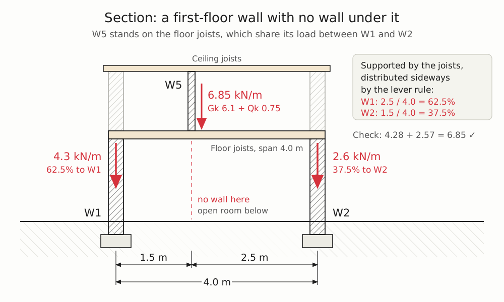
Per metre run of the upper wall:
| Gk (kN/m) | Qk (kN/m) | Total (kN/m) | |
|---|---|---|---|
| Upper wall | 6.1 | 0.75 | 6.85 |
| Added to W1 (62.5%) | 3.81 | 0.47 | 4.28 |
| Added to W2 (37.5%) | 2.29 | 0.28 | 2.57 |
The two shares add back to 6.85 kN/m (4.28 + 2.57), which is the first thing to check. Rounded, that is about 4.3 kN/m on W1 and 2.6 kN/m on W2. Add them to W1 and W2 on top of the floor load those walls already carry from their own tributary strips, then carry on down to the footings.
Two things the takedown does not settle. First, the joists have to be checked for the point load: at 400 mm centres each joist takes 6.85 × 0.4 = 2.7 kN characteristic, on top of its share of the floor, which a joist sized for floor load alone may not carry. Second, if the upper wall only runs part of the way across the room, the extra load only applies to the length of W1 and W2 opposite it, not to the whole wall.
Case 2: the wall runs along the joists, on a beam
Here the upper wall runs parallel to the joists, so it would sit on a single joist, or between two. That is not enough, so it is supported by a beam that spans 3.6 m from W1 to W2 below. The beam replaces one joist, so it also carries a 0.4 m strip of floor.
Line load on the beam:
| Item | Gk (kN/m) | Qk (kN/m) |
|---|---|---|
| Upper wall | 6.1 | 0.75 |
| Floor strip, 0.4 m × (0.6 dead, 1.5 imposed) | 0.24 | 0.6 |
| Beam self-weight allowance | 0.3 | |
| Total | 6.64 | 1.35 |
Each end reaction, for a simply supported beam, is half the span times the line load:
Gk = 6.64 × 3.6 / 2 = 12.0 kN
Qk = 1.35 × 3.6 / 2 = 2.4 kN
Characteristic total  = 14.4 kN
Design (1.35G + 1.5Q) = 1.35 × 12.0 + 1.5 × 2.4 = 19.8 kN
So W1 and W2 each get a point load of 14.4 kN characteristic where the beam bears on them. That changes what you need to check below:
- The bearing. The masonry directly under the beam end takes the full 19.8 kN design load, usually through a padstone. This is a local check, done with design loads.
- The wall below. The point load spreads out as it goes down, roughly at 45° each side. Through a full 2.4 m storey of solid wall, starting from a 440 mm padstone, it spreads over about 0.44 + 2 × 2.4 ≈ 5.2 m. That adds only about 14.4 / 5.2 ≈ 2.8 kN/m at the footing.
- Openings and wall ends. If a door or window, or the end of the wall, cuts off the spread on one side, the load spreads over half the length and the extra line load roughly doubles. A narrow pier between two openings can end up taking the whole 14.4 kN.
Nothing from the upper wall reaches the ground directly under it. If there is an old footing on that line (from a wall that was taken out, say), it carries none of this load.
Writing it into the takedown
Keep offset walls visible on the calculation sheet, because they are where a checker will look first.
- Stop the upper wall at its floor. Give it a reference (W5, say) and total it at the base as usual.
- Name the element that carries it. "W5 on joists J1, 1.5 m from W1" or "W5 on beam B2, span 3.6 m".
- Show the split. The lever-rule shares, or the beam reactions, with Gk and Qk kept separate.
- Add the shares where they land, as line loads (case 1) or point loads (case 2), and say which.
- Check the books balance. Everything W5 carried must turn up somewhere below. The manual load takedown article notes the same thing for transfer structures generally: the takedown above the transfer is still valid, but everything below it has to be re-thought.
The worked example is a house where everything stacks. Most real houses have at least one wall that doesn't, so it is worth checking for them before you start the numbers.
FAQ
What happens to the load from a wall that isn't above another wall?
It is supported by the floor it sits on, and the joists or a beam distribute it sideways to their supports. The walls either side pick it up in proportion to how close they are. Nothing comes straight down under the wall itself. The supporting joists or beam must be checked for that extra load.
Can floor joists support a wall upstairs?
Sometimes. A light partition is usually covered by the floor's partition allowance. A loadbearing wall that crosses the joists puts a point load on each one, which often needs bigger or doubled joists. A loadbearing wall running along the joists normally needs a beam or multiple joists under it. An engineer should check either case.
How do I split a load between two supports?
Use the lever rule. For a load at distance a from support A on a span L, support B takes a / L of the load and support A takes the rest, (L − a) / L. A load 1.5 m from one end of a 4.0 m span puts 62.5% on the nearer support and 37.5% on the further one.
Does a beam reaction need its own foundation?
Not always. On a continuous strip footing the point load spreads through the wall above at about 45°, so the footing sees only a modest increase. It matters when the beam lands on a short pier or next to an opening. Then the load is concentrated and the footing under that pier may need widening.
LoadTakedown imports each page of a PDF as its own level and carries the loads down level by level, with running totals on each wall. Try it on your own drawings at LoadTakedown.
Sketch your structure straight onto a PDF plan and get tributary loads for every wall and level, instantly.
Open LoadTakedown