Distributing Point and Patch Loads on Two-Way Slabs
19 October 2026 · 5 min read
How LoadTakedown distributes point and patch loads on a two-way slab to its supports, and how the method compares with elastic plate theory.
The 45° rule distributes a two-way slab's uniform load to its supporting walls. It does not address concentrated or partial loads such as a water tank, a post bearing on the slab or an area of plant. This note sets out the method LoadTakedown uses for those loads and compares it with two common alternatives and with elastic plate theory.
Example
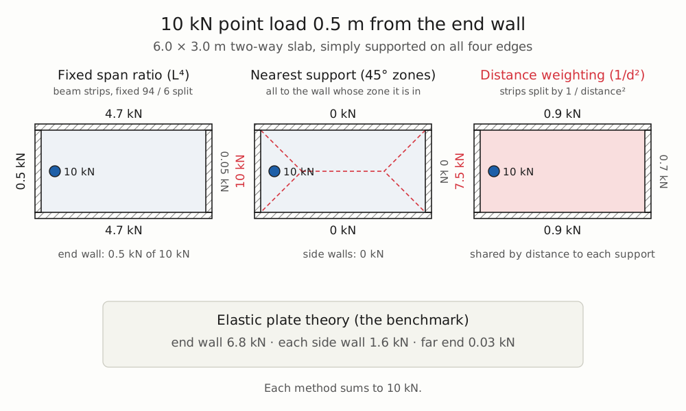
A 6.0 × 3.0 m slab is simply supported on walls on all four edges. The 6.0 m walls are the side walls and the 3.0 m walls the end walls. A 10 kN point load is applied at mid-width, 0.5 m from one end wall.
Fixed span ratio. The load is divided between two orthogonal beam strips, a 3.0 m strip spanning between the side walls and a 6.0 m strip spanning between the end walls, using the Rankine–Grashof ratio ly⁴ : lx⁴ (short span : long span). This gives 94% to the 3.0 m strip and 6% to the 6.0 m strip. Each strip then distributes its share to its ends by the lever rule. The near end wall receives 0.5 kN and each side wall 4.7 kN. The ratio is derived for a uniform load and takes no account of the load's position.
Nearest support (45° zones). The whole load is assigned to the wall whose 45° zone contains it, so the near end wall receives 10 kN and the side walls nothing. The result changes abruptly as the load crosses a zone boundary.
Distance weighting. The load is divided between the two strips in proportion to the sum of 1 / d² for each strip's two supports, where d is the distance from the load to the support along the strip. The 6.0 m strip's weight is 1/0.5² + 1/5.5² = 4.03 and the 3.0 m strip's is 2/1.5² = 0.89, so the 6.0 m strip takes 8.2 kN and the 3.0 m strip 1.8 kN. Each strip then distributes its share by the lever rule. The near end wall receives 7.5 kN, the far end wall 0.7 kN and each side wall 0.9 kN.
The elastic solution for a simply supported rectangular plate (Timoshenko and Woinowsky-Krieger, Theory of Plates and Shells) gives 6.8 kN to the near end wall and 1.6 kN to each side wall. Distance weighting is the closest of the three, with a largest error of 0.7 kN against 3.2 kN and 6.3 kN for the other two methods. Plate reactions here are the integrated edge shear, which is the Kirchhoff edge reaction with the corner forces shared between adjacent edges.
Comparison with plate theory
A patch load is treated as a set of small point loads. A patch covering the whole slab can therefore be checked directly against the uniform-load solution. For 10 kN/m² over the 6.0 × 3.0 m slab (180 kN in total):
| Method | Each side wall (kN) | Each end wall (kN) |
|---|---|---|
| Fixed span ratio | 84.7 | 5.3 |
| Nearest support | 67.5 | 22.5 |
| Distance weighting | 63.0 | 27.0 |
| Plate theory | 65.7 | 24.3 |
Each method is an approximation to the plate solution, and each suits a different kind of load. The 45° rule is the better approximation for a load spread over the whole slab, and distance weighting for a load on part of it. It is therefore important to enter each load with the appropriate loading type: a load covering the whole slab as a slab load, and a local load as a point, line or patch load.
The three methods were also compared with plate theory for whole-slab loads at four aspect ratios, of which two are shown, and for 80 random patches on slabs from 3 to 9 m. The figures below are the largest error at any one support, as a percentage of the applied load:
| Method | Square slab | 2 : 1 slab | Patches, mean | Patches, worst |
|---|---|---|---|---|
| Fixed span ratio | 0% | 10.6% | 12% | 56% |
| Nearest support | 0% | 1.0% | 22% | 55% |
| Distance weighting | 0% | 1.5% | 5% | 9% |
For patch loads, distance weighting was within 10% of plate theory in all the cases tested.
Method used in LoadTakedown
- The slab's own uniform load is distributed by nearest-support tributary areas. On a rectangular panel these are the 45° zones.
- Point loads are divided between two strips, one along each span direction of the slab, in proportion to the sum of 1 / d² for each strip, where d is the distance from the load along the strip to the first support on each side. Each strip then distributes its share by the lever rule. Where a strip finds a support on one side only, that support takes the strip's full share.
- Additional nearby supports. Any support closer to the load than those found along the strips, such as a wall that ends short of the load or a column beside it, is given a weight of 1 / d² − 1 / d₀² alongside the strip weights, where d₀ is the distance to the nearest support found along the strips. Its share therefore rises from zero as the load approaches it. This has no effect on a rectangular slab supported on all four edges.
- Flat slabs on columns treat the lines between adjacent columns as beams, so a load within a bay is shared between its four corner columns.
- Patch and line loads are divided into small elements, each distributed as a point load.
- The slab is taken as simply supported at every support. Continuity is not modelled. It would increase the load on internal supports, by 25% on the central support of two equal spans under uniform load.
Limitations
The comparison assumes rigid, simply supported edges. Continuity over internal walls, flexible supporting beams and openings in the slab all alter the distribution, and a finite element analysis is more appropriate where these govern. Where a wall stops part-way across a slab, the share it takes changes abruptly as the load passes its end; a plate shares such a load more smoothly. The method determines the load path only. Punching shear and local bending under concentrated loads must be checked separately.
Sketch your structure straight onto a PDF plan and get tributary loads for every wall and level, instantly.
Open LoadTakedown