Point Loads from Steel Posts in Extensions
12 October 2026 · 8 min read

How to take a steel post in a kitchen extension down to its pad footing: add the beam reactions, keep Gk and Qk apart, and size the pad. Worked to 77 kN.
A steel post carries whatever the beams on top of it deliver, so its load is the sum of the beam end reactions that land on it, plus its own small self-weight. Work out each beam's reaction, add them at the post, keep the permanent and variable parts separate, then take the total straight down to its own pad footing. The pad is sized with the characteristic load, and the steel, base plate and concrete under the plate are checked with the design load (1.35G + 1.5Q).
Posts turn up in most UK kitchen extensions where the rear wall, and often a side wall, is knocked through. The beams over those openings usually meet at a corner, and the corner has nothing left under it but a post.
Taking out both walls at a corner also removes the masonry that braced that corner of the house sideways. The engineer has to show how the house stays stable, often with a moment-resisting (goalpost) frame or retained piers, as well as checking the post for vertical load.
| Stage | Example value | Basis |
|---|---|---|
| Beam B1 reaction at the post | 33.0 G + 17.2 Q = 50.2 kN | Characteristic |
| Beam B2 reaction at the post | 20.6 G + 5.3 Q = 25.9 kN | Characteristic |
| Post at its base | 54.0 G + 22.5 Q = 76.5 kN | Characteristic |
| Post at its base | 106.7 kN | ULS, 1.35G + 1.5Q |
| Pad footing | 1.0 × 1.0 m, 89 kN/m² | Characteristic, 100 kN/m² allowable |
These are typical values, for illustration. Check them with a competent engineer for any real design.
What is the example?
A two-storey semi-detached house, 8.0 m deep, with a gable end and a single-storey extension that wraps round the back corner. Two walls are opened up at that corner:
- B1 replaces the rear wall over a 4.2 m span, from a padstone on the party wall to the post.
- B2 replaces part of the flank (gable) wall over a 3.0 m span, where the extension wraps round the corner, from the post to a padstone on the remaining flank wall.
- Post P1 stands at the corner where B1 and B2 meet, on a new pad footing.
The original rear wall carried the first floor and the roof. All of that now goes through B1. The beam to foundation article covers the padstone end of a beam like this. This one covers the post end.
What does each beam carry?
Build the line load on each beam from loaded widths, as in loaded width. Keep Gk and Qk in separate columns from the start.
B1, rear wall opening, 4.2 m span:
| Item | Working | Gk (kN/m) | Qk (kN/m) |
|---|---|---|---|
| House roof, trusses span 8.0 m | 0.9 × 4.0 and 0.6 × 4.0 | 3.6 | 2.4 |
| First floor, joists span 4.0 m onto a spine wall | 0.6 × 2.0 and (1.5 + 0.8) × 2.0 | 1.2 | 4.6 |
| Cavity wall above, 2.5 m high | 3.5 × 2.5 | 8.8 | |
| Extension flat roof, 4.0 m span | 0.75 × 2.0 and 0.6 × 2.0 | 1.5 | 1.2 |
| Beam self-weight | assumed | 0.6 | |
| Total | 15.7 | 8.2 |
B2, flank wall opening, 3.0 m span:
| Item | Working | Gk (kN/m) | Qk (kN/m) |
|---|---|---|---|
| Cavity wall above, 2.5 m high | 3.5 × 2.5 | 8.8 | |
| Gable above eaves, average 1.0 m high (35° pitch) | 3.5 × 1.0 | 3.5 | |
| First floor strip | 0.6 × 1.5 and (1.5 + 0.8) × 1.5 | 0.9 | 3.5 |
| Beam self-weight | assumed | 0.5 | |
| Total | 13.7 | 3.5 |
The area loads are the typical UK domestic values from the table in the manual load takedown article, taking the upper 0.8 kN/m² partition allowance on the first floor to be cautious. All the masonry above each opening, including the gable over B2, is taken on the beam, with no allowance for arching. Treating the gable triangle as a uniform load is conservative at the post end. The wrap-round part of the extension has its flat roof spanning front to back onto its own walls, so it puts nothing on B2. If it bears on B2 instead, add it in the same way as on B1.
The flat roof's 0.6 kN/m² is the uniform figure. Snow drifts against the house wall, right over B1, so check the drift case in BS EN 1991-1-3 Annex B; see UK snow load.
What does the post carry?
For a simply supported beam, each end reaction is half the span times the line load. Work them out for Gk and Qk separately.
B1   Gk = 15.7 × 4.2 / 2 = 33.0 kN
     Qk =  8.2 × 4.2 / 2 = 17.2 kN

B2   Gk = 13.7 × 3.0 / 2 = 20.6 kN
     Qk =  3.5 × 3.0 / 2 =  5.3 kN
Add the reactions at the post, plus the post's own weight. A 100 × 100 SHS post 2.4 m high weighs less than half a kN.
Post Gk = 33.0 + 20.6 + 0.4 = 54.0 kN
Post Qk = 17.2 + 5.3        = 22.5 kN

Characteristic      = 54.0 + 22.5               = 76.5 kN
ULS (1.35G + 1.5Q)  = 1.35 × 54.0 + 1.5 × 22.5  = 106.7 kN
Applying 1.5 to every variable load at once is slightly conservative; see beam to foundation for the 6.10a and 6.10b alternative.
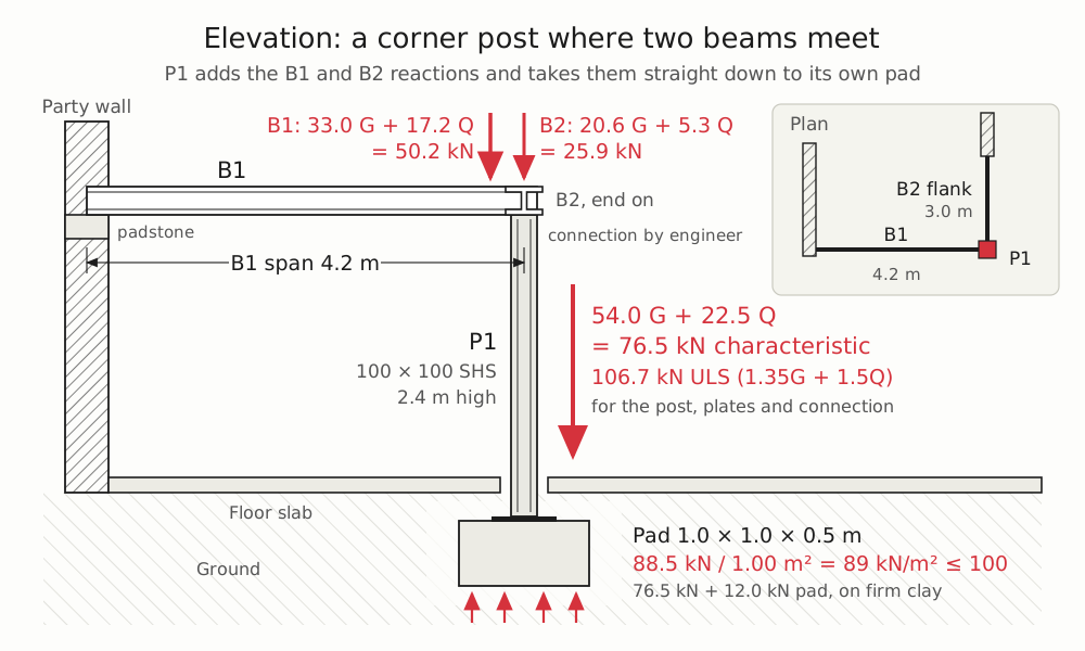
The other ends of B1 and B2 put the same reactions on the party wall and the flank wall, through padstones. Those are point loads on walls, and they spread down the wall as the beam-to-foundation article shows. The post's load does not spread along a wall: it arrives on the pad as a concentrated load through a base plate.
Check: B1 carries 23.9 × 4.2 = 100.4 kN and B2 carries 17.2 × 3.0 = 51.6 kN, 152.0 kN in all. That load leaves through the post (76.1 kN before its self-weight) and the two padstones (50.2 + 25.9 = 76.1 kN), 152.2 kN in all. That matches to rounding, so nothing has been lost or counted twice.
Why can't the post sit on the floor slab?
A ground-bearing floor slab is usually 100 to 150 mm of concrete on hardcore. It is not designed for a 77 kN point load, and it will crack and settle under one. A post needs its own foundation: a mass concrete pad under the slab, a pad cast into the new extension footings, or a designed local thickening of the slab.
The same goes for an existing strip footing. A post at the end of an old wall often lands on that wall's footing. A 600 mm strip that carries 30 kN/m along the wall has little spare for an extra 77 kN on one spot, so it is usually broken out locally and replaced with a bigger pad. In this example P1 stands right on the old corner footings. Breaking them out needs the retained walls propped, and the new pad should go no shallower than the footings next to it.
How big does the pad need to be?
Divide the characteristic load at the underside of the pad by the allowable bearing pressure. Add the pad's own weight to the post load first.
Take a firm clay with a presumed allowable bearing pressure of 100 kN/m², and try a 1.0 × 1.0 m pad, 0.5 m thick:
Pad weight     = 1.0 × 1.0 × 0.5 × 24  = 12.0 kN
Total at base  = 76.5 + 12.0           = 88.5 kN
Pad area       = 1.0 × 1.0             = 1.00 m²
Pressure       = 88.5 / 1.00           = 89 kN/m²  ≤ 100  OK
A 0.9 × 0.9 m pad would not do: (76.5 + 9.7) / 0.81 = 106 kN/m², over the 100 allowed.
The backfill over the pad roughly replaces the soil that was dug out, so it is left out here. On the gross convention used in foundation load from a wall you would add it: about 0.5 m of fill over a pad founded at 1.0 m is roughly 9 kN, giving about 98 kN/m², still within the 100 allowed. On clay the pad also has to go deep enough to avoid shrinkage and tree roots, typically at least 0.9 to 1.0 m in the UK and often much deeper near trees. That depth is set by the ground (NHBC Chapter 4.2 is the usual reference) rather than by the load.
The ULS load of 106.7 kN is for the steelwork: the post, the beam-to-post connection, the base plate and the concrete directly under it. Don't use it for the bearing pressure, and don't use the characteristic load for the steel. In a house, the post and beams supporting the floor above usually also need 30 minutes' fire protection (board or intumescent paint), and the beams must be fixed to the top of the post so it is held in both directions.
What if the post is upstairs?
A post higher up the house, such as one holding up a ridge beam in a loft conversion, has no foundation of its own. Its load becomes a point load on whatever is underneath it:
- On a wall. Treat it like a beam end: a padstone, then spread down the wall. See beam to foundation.
- On a beam, or joists designed for it. It is a transfer. The beam or joists take the point load sideways to their supports, as shown in walls that don't line up. Don't stand a post on standard floor joists without checking them, because a point load is very different from the floor load they were sized for.
- On another post. The loads add, and the bottom post takes both down to the pad.
Whichever it is, the takedown has to follow the post load all the way down. A post that stops at a floor with no named support underneath is the first thing a checker will ask about.
Writing a post into the takedown
- Give each post a reference (P1, P2) and mark it on the plan.
- List every beam that lands on it, with each reaction split into Gk and Qk.
- Add the self-weight and total at the base.
- Name its support: a pad footing, a wall, a beam or another post.
- Check the books balance. The total load on all the beams should equal what comes out at the posts and padstones.
The check a load takedown article has a total-weight check that catches a post load counted twice or not at all.
FAQ
How do you calculate the load on a steel post?
Add the end reactions of every beam that sits on the post, plus the post's own weight. For a simply supported beam each reaction is half its line load times its span. Keep permanent and variable loads separate so you can use characteristic loads for the footing and factored loads for the steelwork.
What size pad foundation does a steel post need?
Divide the characteristic post load, plus the pad's own weight, by the allowable bearing pressure of the ground. A 77 kN post on firm clay at 100 kN/m² needs about 0.9 m², so a 1.0 × 1.0 m pad. The depth is usually set by the ground and nearby trees, not the load. An engineer and building control should confirm it.
Can a steel post sit on a concrete floor slab?
Not normally. A ground-bearing slab is too thin to take a concentrated load of tens of kN, and it will crack and settle. The post needs its own pad footing below the slab, or a properly designed thickening, checked for bearing and punching.
Do I use factored or unfactored loads for a post footing?
Unfactored (characteristic) loads to size the footing against a presumed allowable bearing pressure. Factored loads, typically 1.35G + 1.5Q, for the post, its connections, the base plate and the concrete under the plate.
LoadTakedown carries beam reactions down as point loads and keeps characteristic and design loads apart at every level. Try it at LoadTakedown.
Sketch your structure straight onto a PDF plan and get tributary loads for every wall and level, instantly.
Open LoadTakedown