How to Read Architectural Drawings for a Load Takedown
12 October 2026 · 8 min read
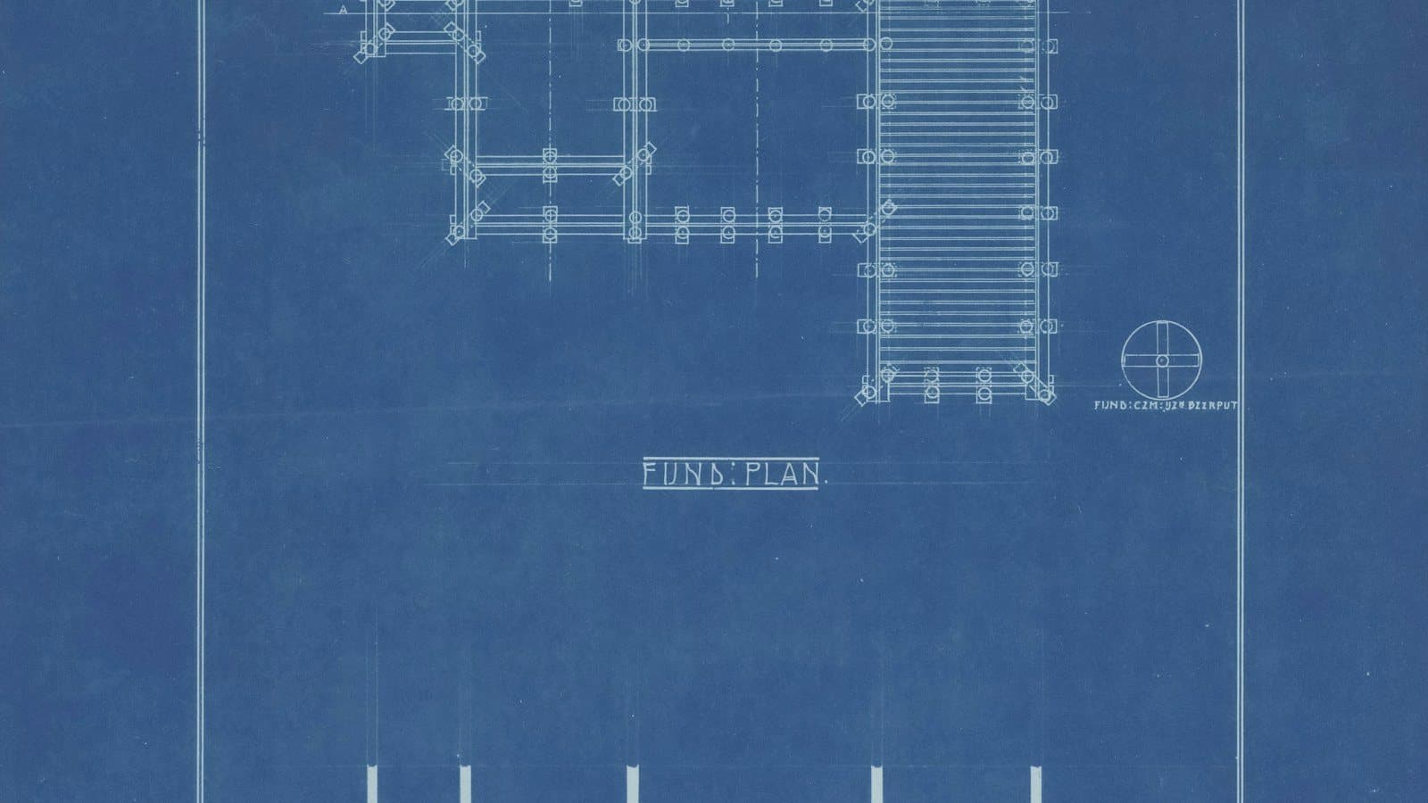
What to pull from an architect's plans before a load takedown: the scale, span directions, loadbearing walls, what stacks, and the storey heights.
Before you can do a load takedown you need five things from the architect's drawings: the scale, the span direction of every floor and roof, which walls are loadbearing, whether each wall stacks on one below, and the storey heights. Most of the rest (furniture, kitchen layouts, the north point) doesn't affect the takedown. But note door and window openings in loadbearing walls, chimney breasts, and the roof and floor construction, because they set lintels, point loads and the loads per square metre.
Architectural drawings are not drawn for structural engineers, so most of these are implied rather than labelled. This guide shows where to find each one and what to do when it isn't shown.
| What you need | Where to look | If it isn't shown |
|---|---|---|
| Scale | Scale bar, title block, a known dimension | Calibrate from a dimension, never from the paper size |
| Span directions | Joist notes, floor arrows, sections, roof plan | Ask. Don't guess |
| Loadbearing walls | Thickness, hatching, what the joists bear on | Assume loadbearing, and check its neighbours without it |
| Stacking | Lay each plan over the one below | Treat as an offset wall |
| Storey heights | Sections, levels on elevations | Use 2.7 m floor-to-floor for a modern house, more for a period house, and say so |
Which drawings do you need?
For a house you normally need every floor plan, the roof plan, at least one section, and the elevations. For alterations you also need the existing plans, because the takedown depends on what is there now as much as on what is proposed.
If there are structural drawings or an engineer's sketch from earlier work, get them too. They often show joist sizes and directions that the architect left off.
Check the scale before anything else
Every dimension you take off a PDF depends on the scale, so set it first and check it.
- Read the title block. "1:50 @ A1" only holds when the sheet is printed at A1. Print it at A3 and it is 1:100 to your ruler, because A3 is half the length of A1. On screen the scale depends on the zoom, so measure with the PDF tool's calibrated ruler, not off the screen.
- Check against a written dimension. Find a dimension string on the drawing, measure the same distance, and compare. If they differ, trust the written dimension.
- Use a known size if nothing is dimensioned. A cavity external wall is about 250 to 350 mm, and a solid brick wall about 225 mm. A standard internal door leaf is 686, 762 or 838 mm wide (926 mm for accessible doors). These are good enough to spot a scale that is off by a factor of two.
Many drawings carry a "do not scale" note. For a takedown you still need lengths, so take written dimensions where they exist and use scaled ones only to fill the gaps.
How do you find the span direction?
The span direction tells you which walls each floor and roof loads. The one-way spanning floors article covers what it means for the load split. On the drawings, look for:
- Joist notes and arrows. A note like "47 × 200 C24 joists @ 400 crs" with a double-headed arrow is the clearest sign. The arrow runs along the joists.
- Sections. If a section shows the joists as a row of small rectangles, the joists run into the page, at right angles to the section line on the plan. If it shows a joist as one long line, they run parallel to the section line. Many architectural sections show the floor only as a hatched band, and then they tell you nothing about direction.
- Stair openings. If the trimming is drawn, the trimmer across the end of the opening runs at right angles to the joists, and the trimming joists along its sides run parallel to them. Architects rarely draw this, so treat it as a check, not a source.
- The roof plan. Trussed rafters are usually drawn or noted on the roof plan. On a simple gable roof they span between the eaves walls, at right angles to the ridge, and usually need no internal support. A traditional cut roof is different: purlins bear on the gable walls and are often propped off internal walls by struts, which puts point loads on walls the plan doesn't flag. Hipped ends change that: see the hipped roof section of the 45° rule article.
On existing houses there is no safe default. In some terraces the joists span side to side between the party walls; in others they run front to back onto a spine wall. Different floors of the same house can differ. If the drawings don't say and you can't see the floor, write the assumption on the sheet and ask for it to be confirmed on site.
Which walls are loadbearing?
Architects often hatch or shade some walls differently, but there is no fixed convention, and hatching usually means "masonry", not "loadbearing". Use these clues together:
- External walls are almost always loadbearing in a house.
- Thickness and line weight. Masonry is usually drawn with a heavier line or a fill, and stud partitions lighter. But a 100 mm block wall and a 100 mm stud wall look much the same on plan, and stud walls can be loadbearing: in timber-frame houses most internal walls are, and in older houses upstairs stud walls often carry ceiling joists or roof struts. Use thickness as a hint, never as proof.
- What the joists bear on. If a span arrow ends at a wall, that wall is loadbearing. If the floor joists run parallel to it, it may carry only itself, but check what is above: ceiling joists, binders, roof struts or a tank can all bear on it.
- Walls that stack. A wall with another wall directly above it on every floor is a strong candidate, because it is often carrying the one above.
If you can't tell, treat the wall as loadbearing. That is conservative for that wall but not for its neighbours, so check the neighbouring walls as if it were not there too, and list the walls you assumed.
Does each wall sit on a wall below?
Lay each floor plan over the one below, at the same scale and lined up on a fixed point such as an external corner. Every loadbearing wall upstairs should have a wall, a beam, or a stated support under it. Any that doesn't is an offset wall, and its load goes into the floor: see walls that don't line up.
Watch for plans that are rotated, cropped, or mirrored between floors. Semi-detached and terraced drawings are often drawn for one house and mirrored for its neighbour.
Existing and proposed
On alteration drawings, demolition is often shown dashed or in a separate colour, and new work in a different fill. Check the legend: dashed lines also commonly mean something overhead, such as a beam or the floor above. For the takedown, three things matter:
- Walls being removed. Whatever they carried now needs a beam. Note the opening width: the beam span is the opening plus its bearings.
- New openings in existing walls. Each needs a lintel or beam, and its ends become point loads on the wall either side.
- New loads on old structure. A loft conversion, a new bathroom or a roof garden adds load to walls and foundations that were never designed for it.
Storey heights and levels
Wall self-weight per metre run is the wall's weight per square metre times its height, so you need the height of each wall. Take floor-to-floor heights from a section, or from the differences between the level marks on the sections and elevations (for example FFL +0.000 and FFL +2.700). External walls run from the foundation to the eaves, and gable walls continue up to the roof line, so include the gable triangle. Internal masonry walls run from floor level to the underside of the floor above; using the floor-to-floor height is simpler and slightly conservative.
If no section is available, assume about 2.7 m floor-to-floor for a modern house. Older houses are often taller (3.0 m or more on the ground floor of a Victorian house), so check on site or use the higher value. Write the value you used on the sheet.
A mark-up checklist
Print the plans, or work on the PDF, and mark these up before any arithmetic:
- The scale, checked against one written dimension.
- A span arrow on every floor and roof area.
- Every loadbearing wall highlighted and given a reference (W1, W2 and so on).
- Beams and lintels drawn and referenced (B1, L1).
- Offset walls circled.
- Storey heights written beside the plan.
- Assumptions listed in one place.
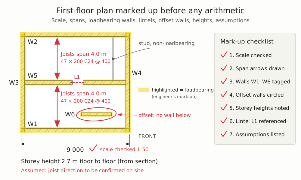
The manual load takedown article shows a plan marked up this way, and then works through the numbers.
FAQ
How do I know which way floor joists run on a drawing?
Look for a joist note or a double-headed arrow on the plan; the arrow runs along the joists. On a section, joists shown as small rectangles run at right angles to the section line. If the stair trimming is drawn, the trimmer across the end of the opening runs at right angles to the joists. If none of these is shown, ask the architect or check on site.
How can I tell if a wall is loadbearing from the plans?
External walls usually are. Internal walls are loadbearing if floor, ceiling or roof members bear on them (joists, binders, purlin struts), or if a loadbearing wall stands on them from above. Hatching on architectural plans usually shows the material, not whether the wall is loadbearing. If you can't tell, assume it is and note the assumption.
What scale are architectural drawings?
House plans are usually drawn at 1:50 or 1:100, and site plans at 1:200 to 1:500. The scale in the title block only applies at the stated sheet size, so a sheet printed at a different size has a different scale. Always check it against a written dimension.
What if the drawings don't show the span direction?
Don't guess. The span direction decides which walls carry the floor, so a wrong guess moves the whole load to the wrong walls. Ask the architect, look for older drawings or a structural survey, or look at the floorboards: they run at right angles to the joists, and the nail lines show where the joists are. Until then, write the assumption clearly on the calculation.
LoadTakedown works directly on the architect's PDF: each page becomes a level, you set the scale from a known dimension, and you trace the walls and spans over the drawing. Try it at LoadTakedown.
Sketch your structure straight onto a PDF plan and get tributary loads for every wall and level, instantly.
Open LoadTakedown