How to Do a Load Takedown for a Two-Story House (US, ASCE 7)
14 October 2026 · 12 min read
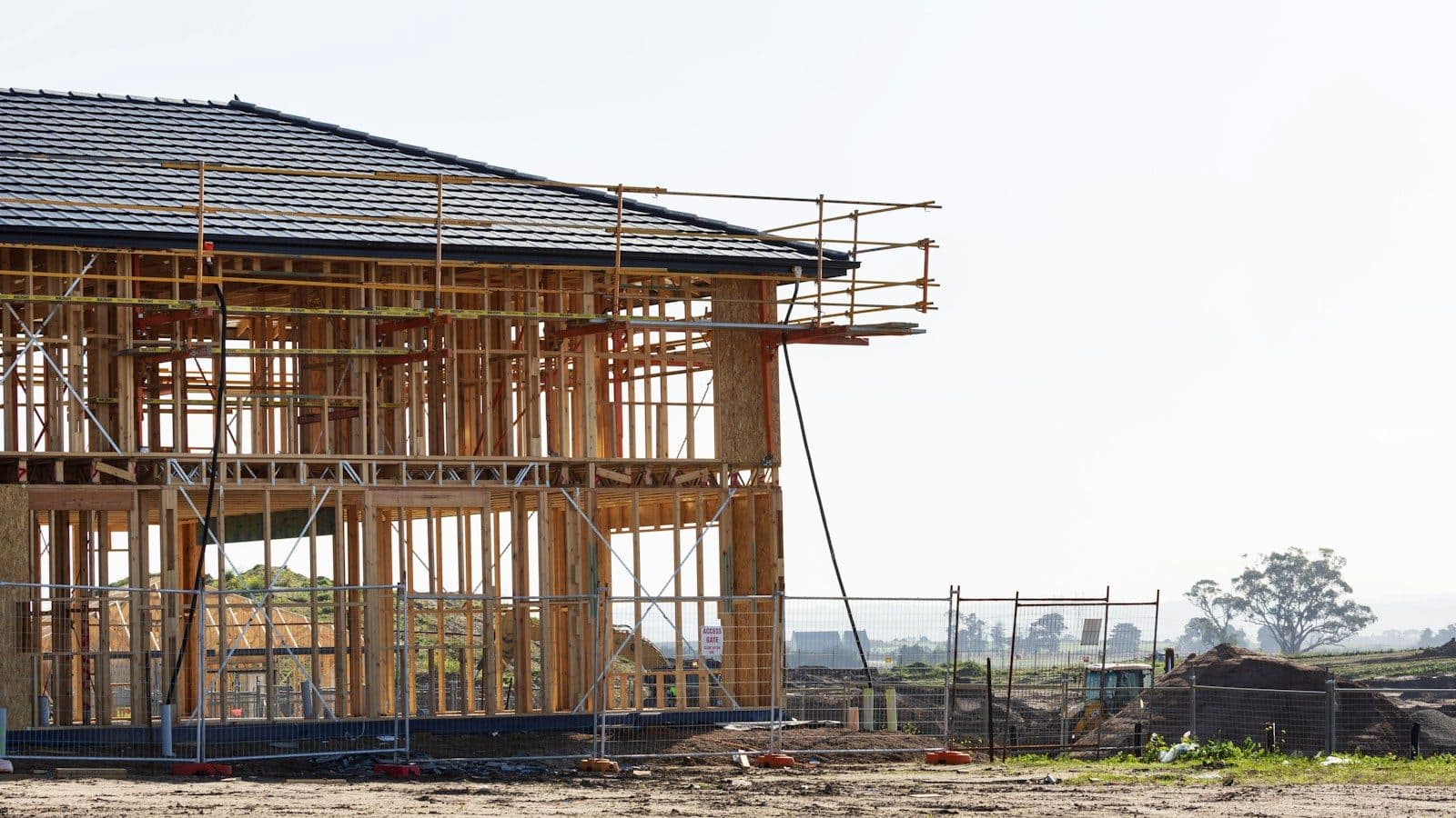
A worked load takedown for a two-story wood-frame house in psf and plf: bearing walls, a header, ASD and LRFD combinations, and footings to the IRC.
To do a load takedown for a house, mark up the plan with span directions and wall references, turn each area load (psf) into a line load (plf) by multiplying it by the tributary width, add each wall's own weight, and keep dead, live and roof live loads in separate columns from the roof down to the footing. For the two-story wood-frame house below, the governing service (ASD) load is about 1,040 plf at the base of the front wall and 906 plf under the interior bearing wall. A 12 in wide footing on soil good for 1,500 psf carries both.
You do not need analysis software for this. A printed plan, a pencil and one sheet of paper are enough to confirm tributary widths, size headers and footings, and get loads you can defend at plan review. This article works through the whole process in US units, to ASCE 7 and the International Residential Code (IRC).
What is a load takedown?
A load takedown traces every gravity load in a building down to the soil. You start at the roof and work down through trusses, joists, headers, beams and bearing walls until the loads reach the footings.
It has three steps:
- Find the load paths. Decide which member supports which load: subfloor to joists, joists to bearing walls and beams, walls and posts to footings.
- Work out the tributary widths. The tributary width is the strip of floor or roof that a wall or beam supports. It turns an area load in psf into a line load in plf.
- Add the loads down the building. Combine each level with the wall self-weight to get the load at the base of each wall, post or column.
If load paths are new to you, the introduction to load takedown covers them first.
What does the example house look like?
The house is 40 ft long and 28 ft deep, two stories, wood-framed, on a slab-on-grade with continuous footings.
- Roof: trusses at 24 in o.c. clear-span 28 ft from the front wall W1 to the rear wall W2, with 1 ft 6 in overhangs. Pitch 6:12.
- Second floor: joists span 16 ft from W1 to the interior bearing wall W3, and 12 ft from W3 to W2.
- First floor: a slab-on-grade. It bears straight on the soil, so it adds nothing to the walls or footings and drops out of the takedown.
- Header H1: a 6 ft wide opening in W1 at the first story.
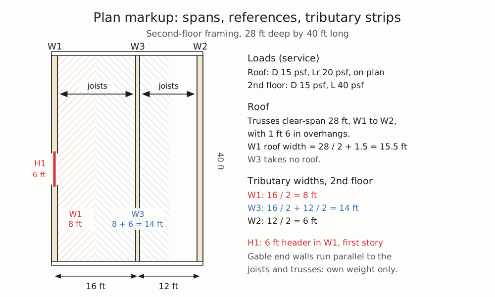
Three things should be on every markup:
- A span direction on every floor and roof zone. Joists only load the walls they bear on. The gable end walls run parallel to the joists and trusses, so they carry their own weight and very little else. One-way spans explains how to tell which way a floor spans.
- A reference on every supporting member. W1, W2, W3, H1. A plan reviewer cannot follow numbers that have no reference.
- The tributary strip, shaded. For a simply supported joist it is half the span each side of the wall. Tributary regions covers the geometry.
What loads go into a US house takedown?
These service (unfactored) loads come from ASCE 7 Table 4.3-1 and IRC Table R301.5 for live loads, and from typical material weights for dead loads. They are typical values; check them with a licensed engineer and against the actual assembly. The typical US floor and roof loads article builds each one up layer by layer.
| Element | Dead, D | Live, L or Lr |
|---|---|---|
| Roof, asphalt shingles on trusses, with ceiling, on plan | 15 psf | Lr = 20 psf |
| Second floor, wood joists, subfloor, finishes, ceiling | 15 psf | L = 40 psf |
| Exterior 2x6 wall, siding, insulation, gypsum | 12 psf of wall | none |
| Interior 2x4 wall, gypsum both sides | 8 psf of wall | none |
A few choices are built into this table:
- 15 psf dead on the roof and floor rounds up the 10 to 11 psf build-ups to cover a second layer of shingles and tile in the bathrooms.
- 40 psf live over the whole second floor, although ASCE 7 allows 30 psf in sleeping rooms. It costs little and survives a change of use.
- 20 psf roof live load, with no reduction. ASCE 7 Section 4.8.2 would allow about 18 psf on this 6:12 roof. Taking 20 is simpler and conservative.
- Snow does not govern. The site is assumed to have a roof snow load below 20 psf. In snow country, use the larger of Lr and S in the combinations below. They are never added together.
- Attic live load is left out. The trusses form an attic without storage, and ASCE 7 Table 4.3-1 says its 10 psf need not act at the same time as other live loads.
The exterior walls are 18 ft tall from the top of the footing to the roof bearing: a 9 ft first story, 1 ft of floor framing and an 8 ft second story.
How do you turn an area load into a line load?
Pick one wall and one floor. Every takedown is this one step, repeated.
The second floor spans 16 ft from W1 to W3. The joists are simply supported, so each wall carries half:
Tributary width to W1 = 16 / 2 = 8 ft
Floor dead  = 15 psf × 8 ft = 120 plf
Floor live  = 40 psf × 8 ft = 320 plf
The trusses span 28 ft from W1 to W2 and overhang 1 ft 6 in. W1 carries half the span plus the overhang:
Roof tributary to W1 = 28 / 2 + 1.5 = 15.5 ft
Roof dead       = 15 psf × 15.5 ft = 232.5 plf
Roof live (Lr)  = 20 psf × 15.5 ft = 310 plf
Keep D, L and Lr apart. The load combinations treat each one differently, so a single "total psf" figure is no use beyond a quick estimate.
How do you work down the stories?
Front wall W1. Add the wall's own weight to the roof and floor:
                         D        L       Lr     (plf)
Roof, 15.5 ft          232.5      -      310
Floor, 8 ft            120.0     320      -
Wall, 12 psf × 18 ft   216.0      -       -
Total at footing       568.5     320     310
Interior bearing wall W3. It carries floor from both sides, so its tributary width is 16 / 2 + 12 / 2 = 8 + 6 = 14 ft. The trusses clear-span over it, so it takes no roof. It is a 2x4 wall, 9 ft tall at the first story, with an 8 ft partition stacked on it at the second story:
                         D        L       Lr     (plf)
Roof                     0        -       0
Floor, 14 ft           210.0     560      -
Wall, 8 psf × 9 ft      72.0      -       -
Partition, 8 psf × 8 ft 64.0      -       -
Total at footing       346.0     560      0
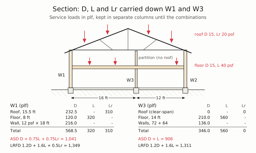
The interior wall carries far more floor live load than the front wall, because it has 14 ft of floor against 8 ft. That is a typical result. A takedown that only looks at the exterior walls will miss it, and the interior footing is often the one that needs the most attention.
Check the roof framing. If the house had rafters and ceiling joists bearing on W3 in place of clear-span trusses, W3 would pick up roof load too. Confirm the framing on the truss layout before relying on either set of numbers.
Which load combinations do you use?
ASCE 7 Chapter 2 gives two sets of combinations. Both use the same service loads. The difference is what you compare the result with.
- ASD (allowable stress design), ASCE 7 Section 2.4. Use for soil bearing, because the IRC presumptive bearing values are allowable values. Wood members are also commonly designed by ASD under the AWC National Design Specification (NDS).
- LRFD (load and resistance factor design), ASCE 7 Section 2.3. Use for steel beams and any member designed by strength.
The combinations that matter for gravity loads on a house are (ASCE 7-16 form):
ASD                                   LRFD
D + L                                 1.4D
D + (Lr or S)                         1.2D + 1.6L + 0.5(Lr or S)
D + 0.75L + 0.75(Lr or S)             1.2D + 1.6(Lr or S) + (L or 0.5W)
In the last LRFD line, ASCE 7 lets you take 0.5 on L in place of 1.0 where the live load is 100 psf or less, which covers a house. ASCE 7-22 changes the snow terms in these combinations to suit its new snow maps, so if snow governs, use the edition your jurisdiction has adopted.
W1 (D = 568.5, L = 320, Lr = 310 plf):
| ASD combination (service) | plf | LRFD combination (factored) | plf |
|---|---|---|---|
| D + L = 568.5 + 320 | 888.5 | 1.4D = 1.4 × 568.5 | 795.9 |
| D + Lr = 568.5 + 310 | 878.5 | 1.2D + 1.6L + 0.5Lr = 682.2 + 512 + 155 | 1,349.2 |
| D + 0.75L + 0.75Lr = 568.5 + 240 + 232.5 | 1,041.0 | 1.2D + 1.6Lr + 0.5L = 682.2 + 496 + 160 | 1,338.2 |
W3 (D = 346, L = 560, Lr = 0):
| ASD combination (service) | plf | LRFD combination (factored) | plf |
|---|---|---|---|
| D + L = 346 + 560 | 906.0 | 1.4D = 1.4 × 346 | 484.4 |
| D + 0.75L = 346 + 420 | 766.0 | 1.2D + 1.6L = 415.2 + 896 | 1,311.2 |
The governing values are in bold: 1,041 plf ASD and 1,349 plf LRFD for W1, and 906 plf ASD and 1,311 plf LRFD for W3.
Keep the ASD and LRFD numbers in separate, labeled columns. Mixing them in one column is the most common error in a hand takedown, and nobody reviewing it can see that it has happened. Characteristic vs design loads explains the same idea in Eurocode terms.
How do you size the header?
Header H1 spans a 6 ft opening in W1 at the first story. It carries everything W1 carries at that level: the roof, the second floor and the second-story wall above it, including the 1 ft of floor framing.
                           D        L       Lr     (plf)
Roof, 15.5 ft            232.5      -      310
Floor, 8 ft              120.0     320      -
Wall above, 12 psf × 9 ft 108.0     -       -
Total on H1              460.5     320     310

ASD:  D + 0.75L + 0.75Lr = 460.5 + 240 + 232.5 = 933.0 plf
      Reaction each end  = 933 × 6 / 2         = 2,799 lb, about 2.8 kips

LRFD: 1.2D + 1.6L + 0.5Lr = 552.6 + 512 + 155  = 1,219.6 plf
      Reaction each end  = 1,219.6 × 6 / 2     = 3,659 lb, about 3.7 kips
Use the ASD load for a sawn-lumber or engineered-wood header designed to the NDS, and the LRFD load for a steel header. For a quick prescriptive check, IRC Table R602.7(1) lists header and girder spans for exterior bearing walls by building width and snow load. Use the clear span plus the bearing length for the design span, and check that the jack studs give enough bearing area.
The 2.8 kip reaction comes down the jack and king studs as a point load. As a feel for its size, it equals about 2.7 ft of the wall's full ASD line load (2,799 / 1,041 = 2.7 ft). A continuous footing normally spreads a load like this. Larger beam reactions need their own footing, as the next example shows.
What about a beam and post?
Say the owner wants an open plan, and W3 is replaced at the first story by a 16 ft beam on posts. The beam carries the second floor and the partition above, but not W3's own first-story wall:
D = 210 + 64 = 274 plf      L = 560 plf

LRFD: wu = 1.2 × 274 + 1.6 × 560 = 328.8 + 896 = 1,224.8 plf
      Mu = wu × L² / 8 = 1,224.8 × 16² / 8 = 39,194 lb-ft, about 39.2 kip-ft
      Ru = 1,224.8 × 16 / 2 = 9,798 lb, about 9.8 kips

ASD:  w  = 274 + 560 = 834 plf
      R  = 834 × 16 / 2 = 6,672 lb, about 6.7 kips
Use Mu and Ru to size a steel beam. Use the 6.7 kip ASD reaction for the post's footing. A square pad 12 in thick, at 150 pcf, weighs 150 psf, so the soil has 1,500 − 150 = 1,350 psf left for the post load:
Area needed = 6,672 / 1,350 = 4.94 sq ft
Try 2 ft 3 in square: 2.25 × 2.25 = 5.06 sq ft
Pressure = 6,672 / 5.06 + 150 = 1,318 + 150 = 1,468 psf ≤ 1,500 psf  OK
That pad sits under the slab at the post. Spreading the 6.7 kips along a 12 in wall footing, as a line-load-only takedown would, understates the load on the soil under the post by a wide margin. Steel post point loads and beam to foundation follow reactions like this to the ground.
Can the soil take it?
Without a soils report, the IRC lets you use presumptive load-bearing values from Table R401.4.1:
| Soil class | Presumptive bearing (psf) |
|---|---|
| Crystalline bedrock | 12,000 |
| Sedimentary and foliated rock | 4,000 |
| Sandy gravel and gravel (GW, GP) | 3,000 |
| Sand, silty sand, clayey sand, silty gravel, clayey gravel (SW, SP, SM, SC, GM, GC) | 2,000 |
| Clay, sandy clay, silty clay, clayey silt, silt, sandy silt (CL, ML, MH, CH) | 1,500 |
If the building official expects soil weaker than 1,500 psf, a soils investigation sets the value. Many jurisdictions amend this table, so check yours.
Compare the governing ASD load with the soil. Take a 12 in wide by 12 in deep continuous footing, which adds 150 psf of concrete over its own area:
W1:  q = 1,041 / 1.0 + 150 = 1,191 psf ≤ 1,500 psf  OK
W3:  q =   906 / 1.0 + 150 = 1,056 psf ≤ 1,500 psf  OK
Both pass on the weakest presumptive soil class. W1 uses about 79 percent of it (1,191 / 1,500). IRC Section R403.1.1 sets a minimum footing of 12 in wide and 6 in thick, and IRC Table R403.1(1) gives prescriptive minimum widths by number of stories, construction type, snow load and soil bearing. A takedown lets you confirm those widths or show why a wider footing is needed. The footings also have to reach below the local frost depth.
Never compare an LRFD load with an allowable bearing pressure. That is the ASD column's job.
When does a hand takedown stop being reliable?
The method assumes one-way spans, simple supports and walls that stack directly on top of each other. Real houses often depart from that.
Walls that do not stack. A second-story bearing wall that lands mid-span on the floor joists breaks the vertical chain. Its load is supported by the joists and distributed sideways to their supports, and the joists need checking for it. Offset walls covers this case.
Girder trusses and hip roofs. A girder truss collects other trusses and delivers a large point load at each end. Read the reactions off the truss design drawings and carry them down as point loads.
Continuous joists. Joists or I-joists running over W3 increase its reaction. For two equal spans the interior reaction is 25 percent higher than the simple half-span split. If W3 is marginal, allow for it.
Snow drifts and lateral loads. Drifts against a taller wall, wind uplift, wind and seismic shear walls, and hold-down forces are outside a gravity takedown, and any of them can govern a connection or footing.
When several of these show up on one plan, use hand calculations to check the key members, and let software carry the rest.
How do you keep a takedown checkable?
- Write the tributary widths, area loads and assumptions next to the results.
- Keep D, L, Lr and S in separate columns until the combinations.
- Keep ASD and LRFD results in separate, labeled columns.
- Round sensibly: 1,041.0 plf becomes 1,041 plf, and a 3,659 lb reaction becomes 3.7 kips.
- Note which walls you assumed carry nothing, and why.
For a review checklist, see how to check a load takedown. The UK version of this article runs the same method in kN/m² with Eurocode factors.
FAQ
How do you calculate the load on a bearing wall?
Multiply each floor and roof area load (psf) by its tributary width onto the wall, usually half the span on each side, to get a line load in plf. Add the wall's own weight (psf of wall times its height). Keep dead, live and roof live loads in separate columns, then apply the ASCE 7 load combinations.
Do I use ASD or LRFD for footings?
ASD. The IRC presumptive soil bearing values in Table R401.4.1 are allowable values, so compare them with ASD loads such as D + L or D + 0.75L + 0.75(Lr or S). Use LRFD loads, such as 1.2D + 1.6L + 0.5(Lr or S), for members designed by strength, typically steel beams.
What soil bearing pressure can I assume without a soils report?
IRC Table R401.4.1 gives 1,500 psf for clays and silts, 2,000 psf for sands and 3,000 psf for sandy gravel and gravel. The building official can require a soils investigation where weaker soils are likely, and many jurisdictions amend the table.
Why does an interior bearing wall often carry more than an exterior wall?
It supports floor from both sides, so its tributary width is half of each adjacent span added together. In the example, W3 picks up 14 ft of second floor against 8 ft for the front wall W1, and 560 plf of floor live load against 320 plf.
What is a plf load?
Pounds per linear foot: the load carried along each foot of a wall, header or footing. You get it by multiplying an area load in psf by a tributary width in feet. A kip is 1,000 lb, so a 2,799 lb header reaction is about 2.8 kips.
LoadTakedown does the same walk down every wall, traced over the architect's PDF, and it takes feet-and-inches input if you work in imperial units.
Sketch your structure straight onto a PDF plan and get tributary loads for every wall and level, instantly.
Open LoadTakedown