Timber Frame House Load Takedown (UK)
27 October 2026 · 11 min read
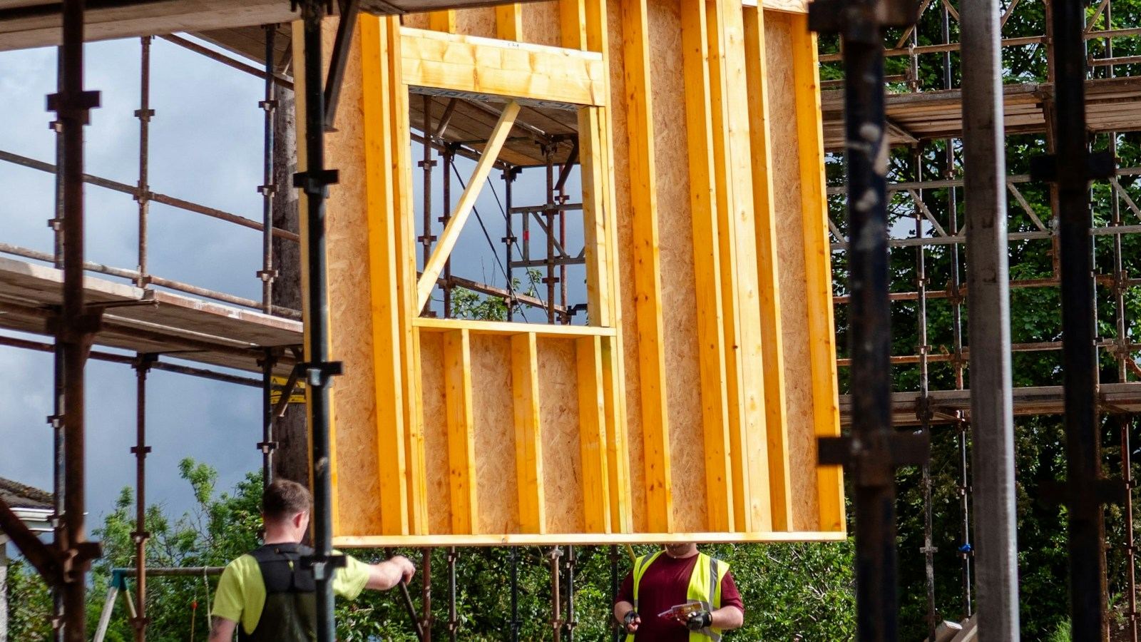
Load takedown for a UK timber frame house: light stud wall build-ups, jamb studs under lintels, and one external wall worked to the footing in kN/m.
A UK timber frame house is taken down the same way as a masonry one, with one big difference: the walls weigh very little. A typical platform-frame inner leaf of studs, OSB sheathing, insulation and plasterboard is about 0.35 kN/m², against about 1.65 kN/m² for a plastered 100 mm block inner leaf. The roof and floors bear on the timber frame, and the brick outer leaf carries only its own weight, straight down to the footing. For the two-storey external wall worked below, the frame delivers 12.9 kN/m at ground level and the brick leaf 9.8 kN/m, so the strip footing sees 22.7 kN/m characteristic (31.6 kN/m ULS) before its own weight.
Platform frame is the usual UK form. Wall panels are made in a factory, one storey high, with the sheathing already fixed. Each floor is built as a deck on top of the panels below, and the next storey's panels stand on that deck.
| Stage | Example value | Basis |
|---|---|---|
| Timber frame inner leaf self-weight | about 0.35 kN/m² | Characteristic |
| Brick outer leaf, 102.5 mm at 19 kN/m³ | 1.95 kN/m² | Characteristic |
| Frame at ground level | Gk 6.5 + Qk 6.4 = 12.9 kN/m | Characteristic |
| Brick outer leaf at ground level | Gk 9.8 kN/m | Characteristic |
| Both leaves at ground level | 22.7 kN/m / 31.6 kN/m | Characteristic / ULS |
| Underside of 600 mm strip footing | 35.0 kN/m, 58 kN/m² | Characteristic |
| Jamb studs beside a 1.8 m window | 15.0 kN / 21.5 kN | Characteristic / ULS |
These are typical values, for illustration. Check them with a competent engineer and the timber frame supplier's design for any real project.
What does a timber frame wall weigh?
Build it up layer by layer, as you would a floor. The figures below are per m² of wall face for a 140 mm external panel. Timber is taken at 4.2 kN/m³, a typical value for C24 softwood, and OSB at 6.5 kN/m³.
| Layer | Working | kN/m² |
|---|---|---|
| 38 × 140 studs at 600 mm centres | 0.038 × 0.14 × 4.2 / 0.6 | 0.04 |
| Sole plate, head binder, top plate, extra studs and noggins | allowance | 0.04 |
| 9 mm OSB sheathing | 0.009 × 6.5 | 0.06 |
| 140 mm mineral wool between studs | 0.14 × 0.3 | 0.04 |
| Breather membrane, vapour control layer, service battens | allowance | 0.03 |
| 12.5 mm plasterboard and skim | allowance | 0.12 |
| Total | 0.33, use 0.35 |
Rounding up to 0.35 kN/m² covers small extras. Two layers of fire-rated plasterboard, a thicker panel or rigid insulation boards can push it towards 0.5 kN/m², so use the supplier's build-up once it is known.
An internal loadbearing stud wall, 38 × 89 studs with plasterboard both sides, comes to about 0.3 to 0.4 kN/m². That matches the stud wall figure in wall self-weight.
Compare that with masonry. A 100 mm medium dense block inner leaf with plaster is 1.40 + 0.25 = 1.65 kN/m², so the timber frame inner leaf is about a fifth of the weight. Over a 2.4 m storey that is 0.8 kN/m against 4.0 kN/m.
Why doesn't the brick outer leaf load the frame?
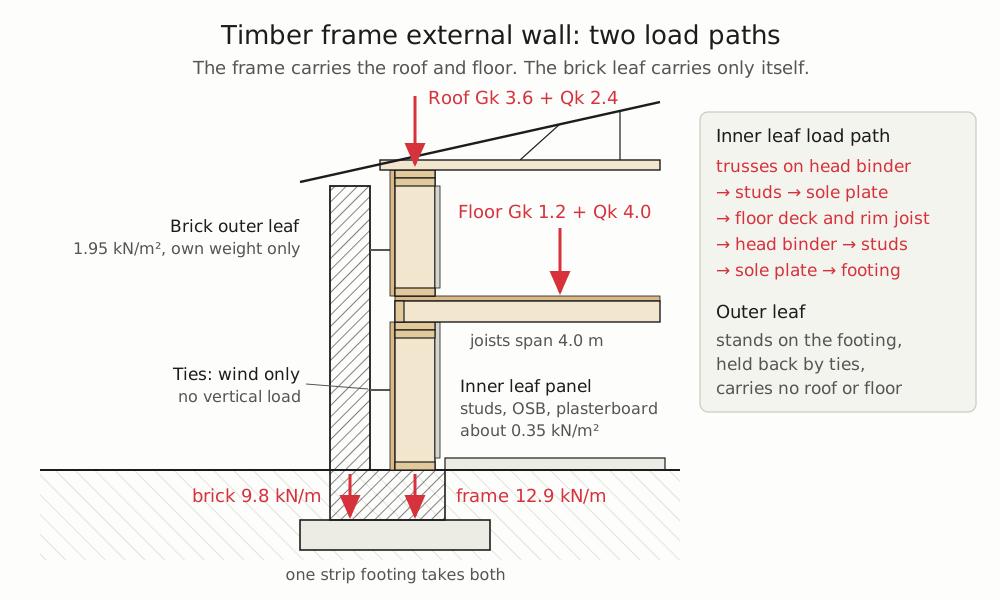
In UK timber frame, the brick outer leaf is a self-supporting cladding. It stands on the substructure and strip footing, and stainless steel wall ties hold it back to the studs. The ties are flexible: they take wind load across the cavity, and they carry no vertical load.
The two leaves have to move independently because the timber frame shrinks. Sole plates, head binders and floor joists all shrink across the grain as they dry, so the frame settles a few millimetres at each floor while the brickwork does not. NHBC Standards Chapter 6.2 sets the gaps needed at window sills, eaves and verges, and where services pass through the brick. If the brick leaf were fixed to the frame, the frame would either hang off the brickwork or crack it.
For the takedown this means two separate load paths:
- Frame inner leaf: roof, floors and its own weight.
- Brick outer leaf: its own weight only. Openings in the brick leaf need their own lintels, which carry only brickwork.
Both arrive at the same strip footing, so you add them there and nowhere above.
How do roof and floor loads reach the studs?
Follow the load through each timber member in turn. In a platform frame it passes through the floor zone at every storey:
- Roof trusses bear on the head binder at the top of the upper panel. Trusses at 600 mm centres usually line up with the studs. The head binder is a second top plate that ties panels together and spreads any truss that lands between studs.
- Upper studs carry the roof and their own panel down to the sole plate.
- The floor deck and rim joist sit between the upper sole plate and the ground-floor head binder. The first-floor joists bear on that head binder too, so the floor load joins here.
- Ground-floor studs carry everything down to their sole plate, which sits on the inner leaf of the substructure blockwork.
Every timber that is loaded across its grain (sole plates, head binders, the rim joist) has to be checked for compression perpendicular to the grain, BS EN 1995-1-1 clause 6.1.5. Under ordinary studs this rarely governs. Under a cluster of jamb studs it often does.
The floor uses the usual timber floor values: Gk 0.6 kN/m², Qk 1.5 kN/m² plus 0.5 kN/m² for movable partitions. The 0.5 band suits timber frame well. A 2.4 m stud partition at 0.35 kN/m² weighs 0.84 kN/m, inside the 1.0 kN/m limit for that band in BS EN 1991-1-1. See typical UK floor and roof loads for the full build-ups.
Worked example: an external wall to the foundation
A detached two-storey timber frame house, 8.0 m front to back:
- Roof: concrete interlocking tiles on trusses spanning 8.0 m between the front and rear walls. 0.9 kN/m² permanent + 0.6 kN/m² imposed on plan (the full 0.6 is conservative above 30° pitch). Loaded width to the front wall = 8.0 / 2 = 4.0 m.
- First floor: timber joists spanning 4.0 m from the front wall to an internal loadbearing stud wall. 0.6 kN/m² + (1.5 + 0.5) kN/m². Loaded width = 4.0 / 2 = 2.0 m.
- Frame: 0.35 kN/m², 2.4 m from first floor to eaves, 2.6 m from ground to first floor.
- Brick outer leaf: 102.5 mm clay brick at 19 kN/m³ = 1.95 kN/m², 5.0 m from ground to eaves.
- Footing: 600 mm wide × 300 mm thick concrete strip, base 1.0 m below ground.
These are the same geometry and roof as foundation load from a wall, so you can compare the two directly. Loaded width explains the half-span widths.
Frame inner leaf, level by level:
Roof           Gk = 0.9 × 4.0  = 3.6     Qk = 0.6 × 4.0 = 2.4
Upper frame    Gk = 0.35 × 2.4 = 0.8
First floor    Gk = 0.6 × 2.0  = 1.2     Qk = 2.0 × 2.0 = 4.0
Ground frame   Gk = 0.35 × 2.6 = 0.9

Frame total    Gk = 6.5 kN/m             Qk = 6.4 kN/m
Characteristic = 6.5 + 6.4                = 12.9 kN/m
ULS            = 1.35 × 6.5 + 1.5 × 6.4   = 18.4 kN/m
Brick outer leaf, on its own:
Outer leaf     Gk = 1.95 × 5.0 = 9.8 kN/m
ULS            = 1.35 × 9.8    = 13.2 kN/m
The brick leaf is taken over its full height with no deduction for windows, which is quick and conservative. Wall self-weight shows how to deduct openings if you want a tighter figure.
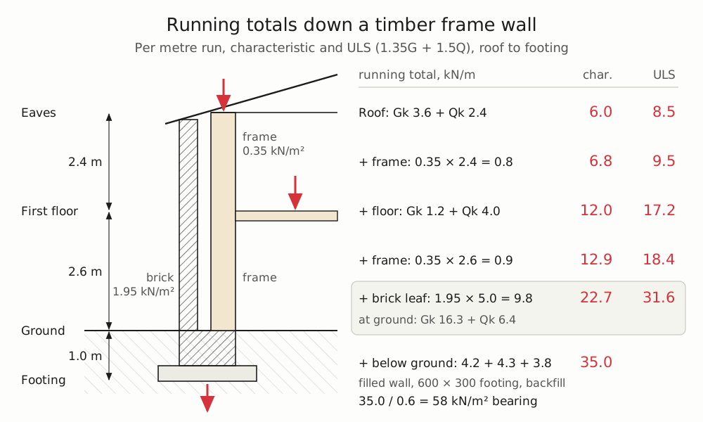
| Level | Item | Gk (kN/m) | Qk (kN/m) | Characteristic running total | ULS running total |
|---|---|---|---|---|---|
| Eaves | Roof, 4.0 m loaded width | 3.6 | 2.4 | 6.0 | 8.5 |
| Upper storey | Frame, 0.35 × 2.4 | 0.8 | 6.8 | 9.5 | |
| First floor | Floor, 2.0 m loaded width | 1.2 | 4.0 | 12.0 | 17.2 |
| Ground storey | Frame, 0.35 × 2.6 | 0.9 | 12.9 | 18.4 | |
| Ground | Brick outer leaf, 1.95 × 5.0 | 9.8 | 22.7 | 31.6 | |
| At ground level | 16.3 | 6.4 | 22.7 | 31.6 |
Check the ULS total from the Gk and Qk columns: 1.35 × 16.3 + 1.5 × 6.4 = 22.0 + 9.6 = 31.6 kN/m. It matches the running total. Applying 1.5 to every variable load at once is slightly conservative; see characteristic vs design loads for the 6.10a and 6.10b alternative.
Below ground, the cavity in the substructure is filled with concrete, and the footing and backfill add their weight. Using the same figures as the masonry example:
Load at ground level                       = 22.7 kN/m
Filled wall below ground  0.3 × 0.7 × 20   =  4.2 kN/m
Footing                   0.6 × 0.3 × 24   =  4.3 kN/m
Backfill on projections   0.3 × 0.7 × 18   =  3.8 kN/m
Total at underside of footing              = 35.0 kN/m

Bearing pressure = 35.0 / 0.6 = 58 kN/m²
Against a presumed allowable bearing pressure of 100 kN/m² for firm clay, that is comfortable. Size the footing with the characteristic load, as here. The ULS figures are for the timber: studs, sole plate bearing and lintels.
The masonry version of this wall reaches 29.8 kN/m at ground level and 42.1 kN/m at the underside of the footing, with a 0.8 kN/m² partition allowance rather than 0.5. Most of the difference is the inner leaf: 1.7 kN/m of timber frame against about 8.3 kN/m of plastered block (1.65 × 5.0) over the two storeys. The frame alone is 12.9 kN/m, and about half of that is imposed load. That high share of variable load matters again at the eaves, as the wind section below shows.
How do point loads at lintels reach the foundation?
A window or door in a stud wall interrupts the studs. A timber lintel (often called a header) spans the opening and puts its two end reactions onto the studs at each jamb. Those reactions are point loads, and they have to go down through the frame to the foundation without being spread out on the way.
Take a 1.8 m window in the ground-floor panel of the example wall, with the lintel spanning about 1.9 m between bearings. The load above the window head is everything at first-floor level: 12.0 kN/m characteristic (Gk 5.6 + Qk 6.4), or 17.2 kN/m ULS. The short panel above the head adds very little and is lost in the rounding.
Lintel reaction    Gk = 5.6 × 1.9 / 2 = 5.3 kN
                   Qk = 6.4 × 1.9 / 2 = 6.1 kN
Characteristic     = 5.3 + 6.1                = 11.4 kN
ULS                = 1.35 × 5.32 + 1.5 × 6.08 = 16.3 kN
The full-height king stud beside the jamb also carries its normal share of the solid wall on the other side, half a stud spacing:
Jamb cluster, characteristic  = 11.4 + 12.0 × 0.3 = 15.0 kN
Jamb cluster, ULS             = 16.3 + 17.2 × 0.3 = 21.5 kN
Ordinary stud at 600 mm       = 12.0 × 0.6        =  7.2 kN characteristic
So the jamb takes about twice the load of an ordinary stud. That is why the lintel sits on one or more short cripple studs (also called jack studs) fixed to a full-height king stud. The frame designer sets the number of studs. Wider openings, and openings under a beam or girder truss, often need three or more.
The point load then has to keep going down:
- Through the sole plate. The cluster bears across the grain, so check bearing on the sole plate under it.
- Through the floor zone. Where a jamb is in an upper storey, the load must cross the floor deck and rim joist. Studs must line up with studs below, with solid blocking (squash blocks) in the floor zone, or with a beam to carry the load across. This is the timber frame version of a load path that stops at a floor, the first thing a checker looks for. See walls that don't line up for transfers.
- Into the substructure. At ground level the sole plate sits on blockwork, which spreads the point load down the wall. Beam to foundation shows the spread.
What about internal loadbearing stud walls?
In this house the internal stud wall carries the first floor from both sides. The trusses span clear between the external walls, so it takes no roof load. Trusses must not bear on internal walls unless the truss design allows for it.
First floor   Gk = 0.6 × 4.0  = 2.4     Qk = 2.0 × 4.0 = 8.0
Stud wall     Gk = 0.35 × 2.6 = 0.9

Total         Gk = 3.3 kN/m             Qk = 8.0 kN/m
Characteristic = 3.3 + 8.0               = 11.3 kN/m
ULS            = 1.35 × 3.3 + 1.5 × 8.0  = 16.5 kN/m
About 70 per cent of this wall's load is imposed, so the ULS figure is almost 1.5 times the characteristic. The wall needs a proper foundation of its own: usually a blockwork substructure wall on a strip footing, or a designed thickening if the ground floor is a slab. Stud walls on the first floor that carry nothing but themselves are partitions, and the 0.5 kN/m² allowance covers them.
Why do wind uplift and holding-down matter more?
The light weight that makes the takedown smaller also leaves less dead load to hold the building down. At the eaves of the example wall, only 3.6 kN/m of roof dead load resists wind uplift on the roof. In an uplift check, that favourable dead load is factored down (0.9 in the UK National Annex to BS EN 1990 for equilibrium), and the imposed load counts for nothing. On an exposed site, or with a lighter roof covering such as slate or metal, the net wind uplift from BS EN 1991-1-4 can approach or exceed it.
Wind on the walls also tries to overturn each braced wall panel, which pulls up one end. So timber frame needs holding-down straps or anchors from the panels into the substructure, truss clips or straps at the wall plate, and sheathing designed for racking. A later article will cover wind uplift and holding-down in more detail.
FAQ
How much does a timber frame wall weigh per m²?
A typical UK external panel of 38 × 140 studs at 600 mm centres, 9 mm OSB, mineral wool and plasterboard weighs about 0.35 kN/m². A heavier build-up with two layers of plasterboard or rigid insulation can reach about 0.5 kN/m². Use the frame supplier's figures once the panel is specified.
Does the brick outer leaf bear on the timber frame?
No. The brick outer leaf stands on its own foundation, normally the same strip footing as the frame, and flexible ties hold it back for wind only. Gaps at sills, eaves and verges let the frame shrink without loading the brickwork. Add the brick leaf's weight to the frame load at the footing.
How many studs go under a lintel in timber frame?
Usually at least one cripple (jack) stud under each end of the lintel, plus a full-height king stud alongside. Wider openings and heavily loaded lintels need two or three. The jamb studs carry about twice an ordinary stud's load, so check bearing on the sole plate under them.
Are foundations smaller for a timber frame house?
Usually the load is lower. In this example 35.0 kN/m reaches the underside of the footing, against 42.1 kN/m for the same wall in masonry. The footing depth is still set by the ground and nearby trees, so the trench often looks the same.
LoadTakedown imports the architect's PDF pages as levels. You trace the walls and spans over the drawing, and it carries the frame loads down level by level with running totals, keeps characteristic and design loads apart, and shows the result in a cross-section view. Try it at LoadTakedown.
Sketch your structure straight onto your drawings and get tributary loads for every wall and level, instantly.
Try the example in the app